University College
Main South Door
I was able to find a few quality plans of University College at University of Toronto that allowed me to continue my project during the pandemic. While it wasn’t one that I was originally planning since it’s not strictly Gothic Revival, it is a good one to include as it has some Gothic Revival elements and it’s at UofT where my Dad and I spent time together when he was a draftsman there and I was attending the Royal Conservatory of Music for summer music theory classes.
I thought I’d start with a study of the main south door, which is very ornate and popular for photographers and tourists. Further down on the page I have included my progress on a 3D rendering of the entire building.
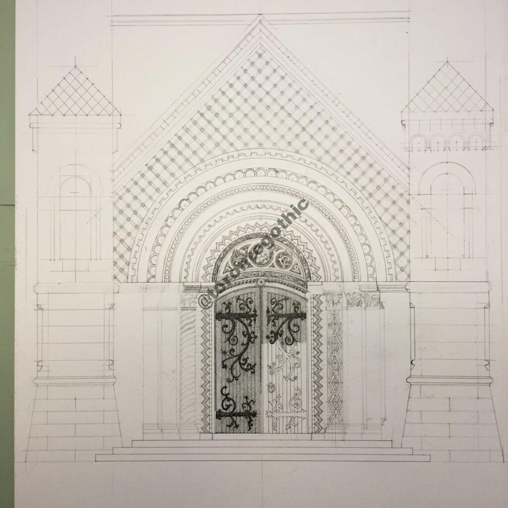
I started with an outline, as shown in Figure 1, which involved a fair amount of compass work and planning out the zig-zag pattern both in the vertical and around the arch.

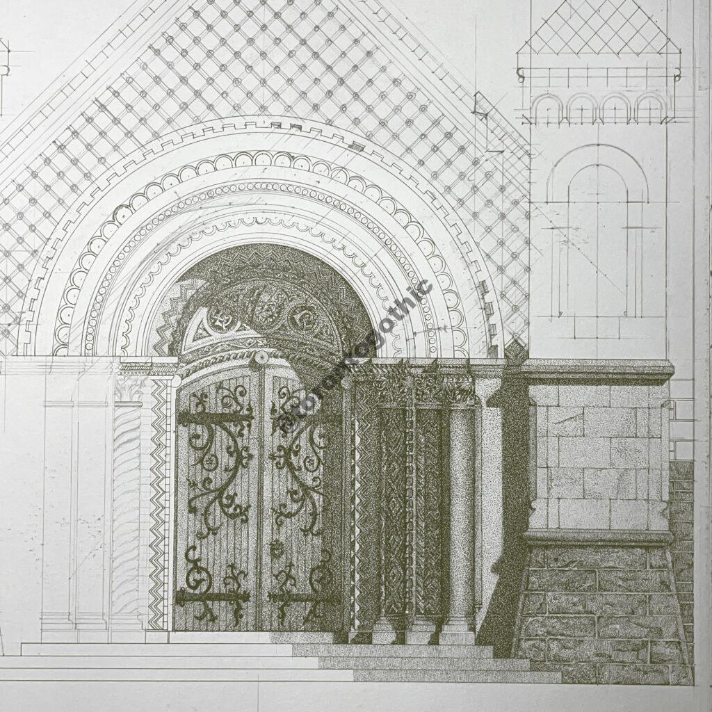
Next, the pillars on either side were added in, along with the patterned peak, and the rear brick wall framing it in. Figure 2 shows this along with the start of some details on the actual wooden door. The lighter lines are pencil while the detailed fill is ink stippling. I’ve also started putting the patterns into the columns beside the door.
One of the main reasons why I wanted to draw this door was because I thought it would look nice when I added shadows, due to the depth from the outer face of the wall to the actual door. Each detailed band is set further back into the building. I plotted all of the shadows manually, set at 45 degrees from each axis (right to left, front to back, top to bottom). The development of the shadows is shown in Figure 3 and Figure 4.

In order to make the shadows as realistic looking as possible I needed to have a cross-section of the vertical profile as well as a floor plan. I drew these in advance (I used them to draw the basic outline) and taped them to the edges of the paper. Then I was able to project the shadow lines and identify where light would hit the various surfaces, and then project those points up/across to their location on the main drawing. The arrangement on my drafting table with some of the projection lines is shown in Figure 5.
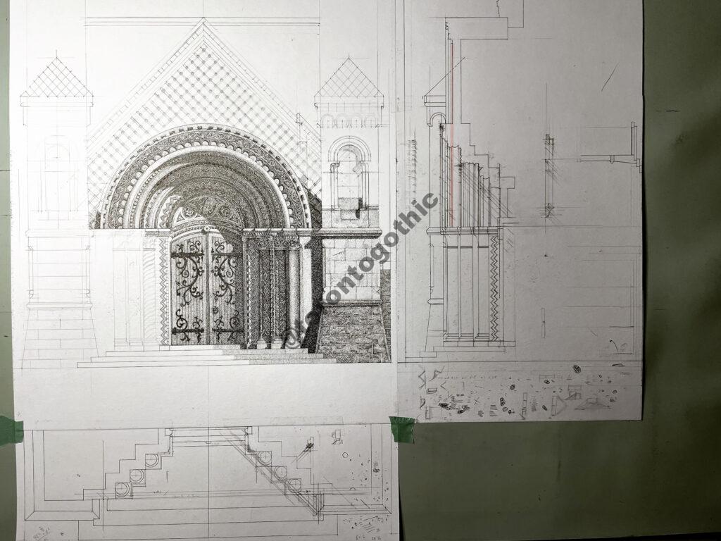
Figure 6 shows how the various shadows came together with the detail of the surfaces. It was important to give the stones the right texture, as there were ones with rough faces, smooth faces, and polished faces, not to mention that there were various different patterns in the columns and capitals.

Finally, the finished study is shown in Figure 7. I completed this over about 4 months.

3D Perspective Drawing
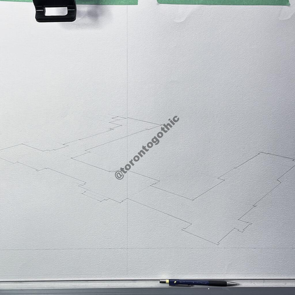
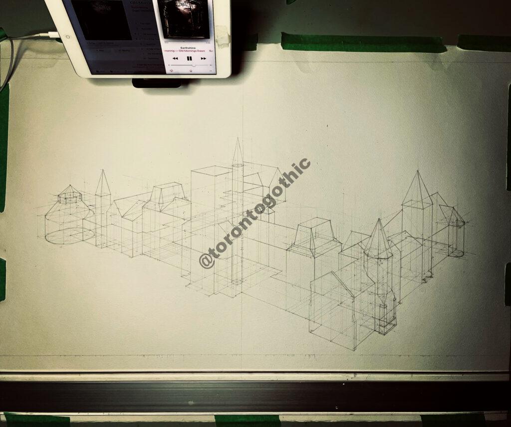
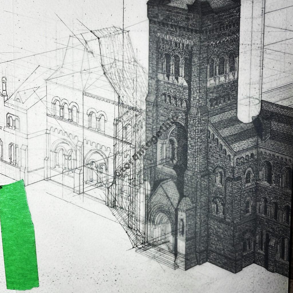
I began drawing the 3D image of the full building on an 18″x24″ page, but since the building was so large I found it was tough to include any details. So I started over using a 22″x30″ page, which still ended up feeling small but was the largest I could find without having to buy a whole roll of paper. I started by putting the floor plan into perspective (2-point perspective), as shown in Figure 8. This is critical to get right. The process could have a whole page dedicated to it, but in short it requires establishing a horizon line, vanishing points, and a station point (or observation point), and also identifying a scale line (the vertical line shown) which matches the scale of the floor plan used in the projection.
The next step was to the add in the vertical dimension using the aforementioned scale line. The vertical line that is visible in Figure 8 is the only vertical that is scaled to the floor plan (and the elevation plans are scaled to the floor plan), so every vertical has to be plotted on this line and projected over to the location it belongs using the vanishing points. This is shown in Figure 9 and Figure 10, with the Figure 10 one being the final “wireframe” of the building. Looks like I was listening to Summoning there…

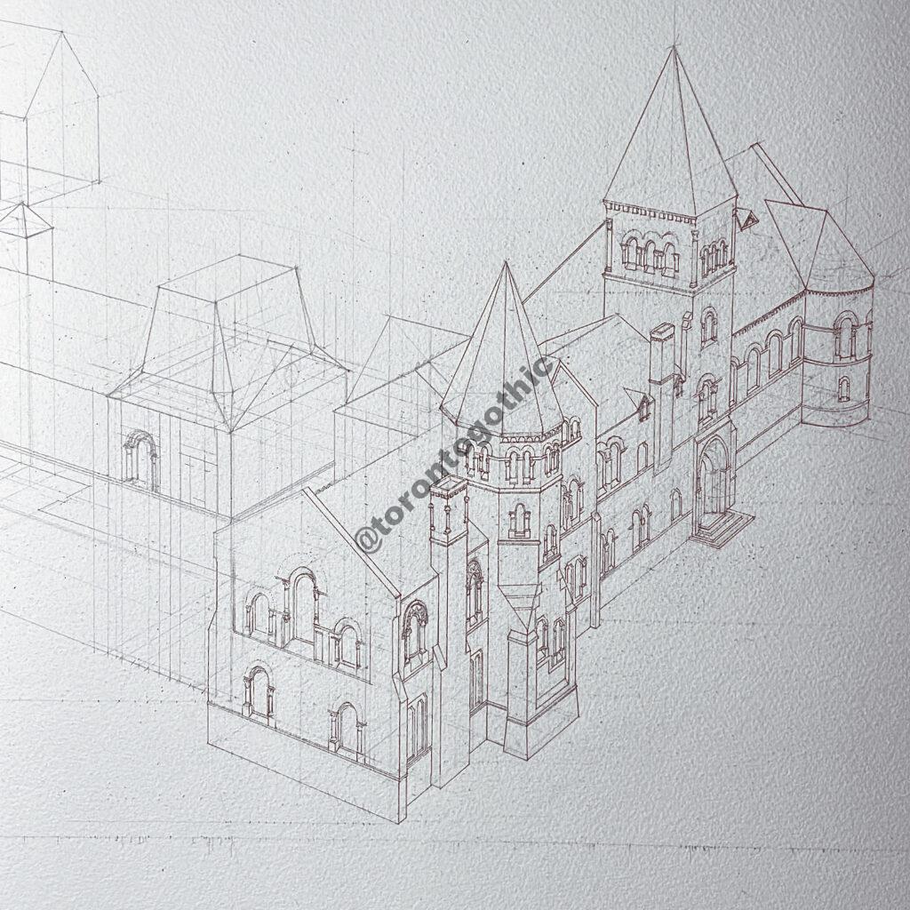
Once the verticals were built in, it was time to start adding the details to the façade. This is the part that takes the most amount of time, particularly since the geometry of each feature has to be determined and then set in perspective. For this I use any photo I can find, often from Google street view or photos I went to the building to take myself. Figure 11 show the progress of outlining the fine details. The dark lines are in ink here.
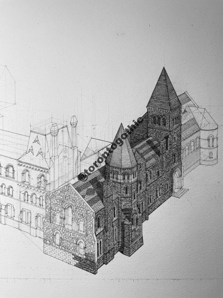
Once the details are outlined then it is possible to proceed with the rendering in ink. This is also a time-consuming step because this is where you have to draw each individual brick. As you can see in Figure 12, I’ve started adding shadows as I go at this point. This is because I need to see the construction lines for the building, including those “inside” the building, which will start to be covered up as the detail gets filled in.
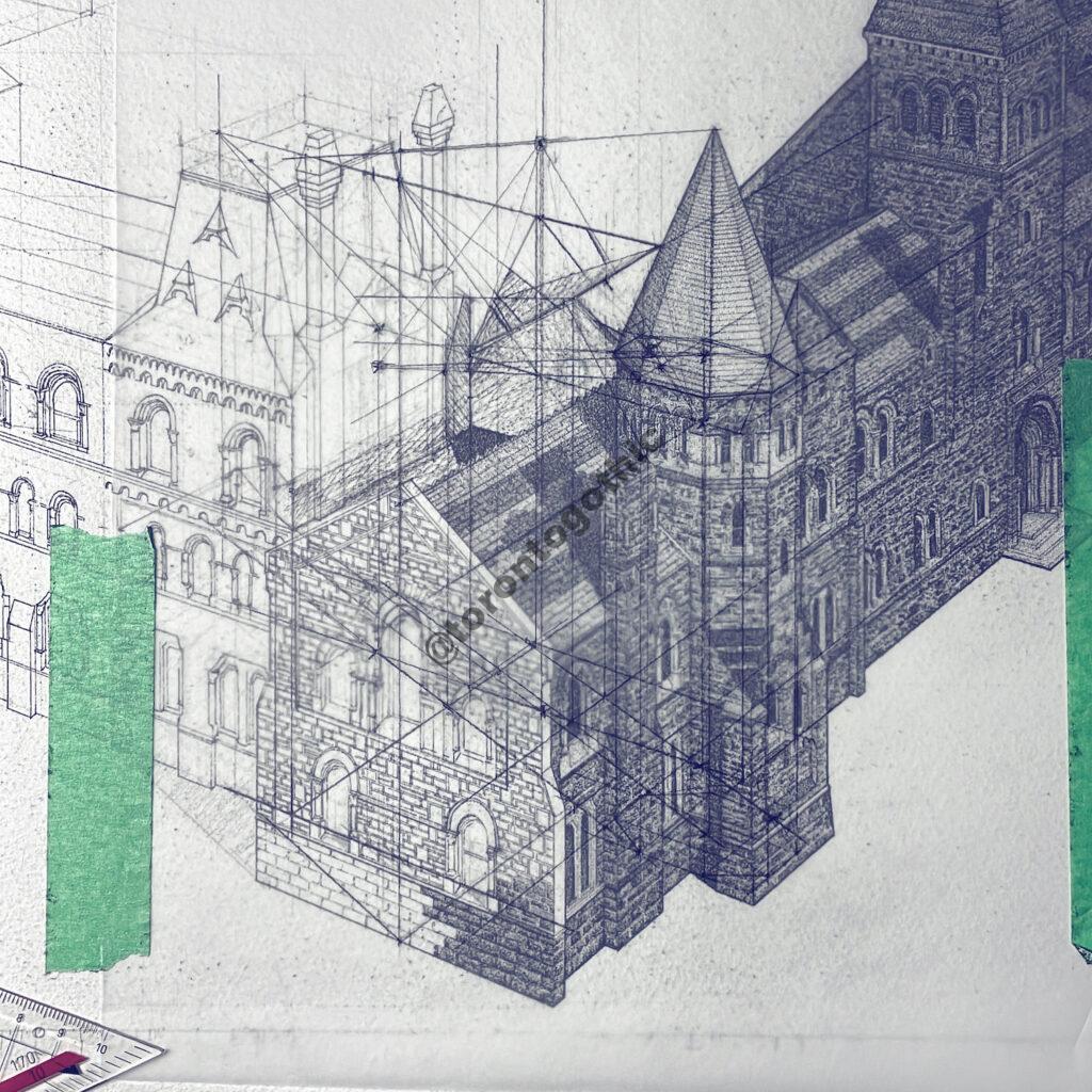
For the shadows, I chose a location for the sun such that the building would cast a nice shadow onto itself. Since the sun is conceptually “behind” me, over my right shoulder, this is done by selecting a point on the horizon line to the left side of the page to give the shadows their direction, and another point on a vertical drawn straight down from that point to indicate where the shadow line terminates (this line can be thought of as the direction of the sun’s rays). The shadows were very complicated for this building, so I used tracing paper to test them out before committing them to ink, as shown in Figure 13. The following picture shows how that looked for one of the most complicated areas. This was complicated because shadows from the tower and surrounding buildings are being cast onto five surfaces (one horizontal, two vertical, and two sloped roofs). You can see how the interior construction lines of the building are required here. A simpler plotting of shadows, from the main tower, is shown in Figure 14.
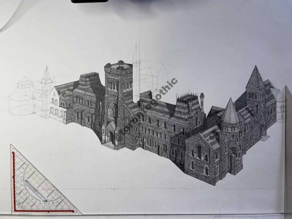
An expanded view showing the partially completed building is shown in Figure 15.
As with previous buildings I’ve completed (Christ Church Deer Park and Old Knox College), I started to put a border around the finished building based on features of the building that I thought were interesting. One of the things that I wanted to include was a rose window I found when reviewing the plans that isn’t visible from outside. I asked the staff there if I could see it, and was able to take a picture (Figure 16). This room was closed so I had to take it through a window. My initial geometry study is shown in Figure 17, and the image in the border is shown in Figure 18. It can be seen there that I added in some images I saw in capitals inside of the building, but adapted them to be flat.


The bottom of the border featured the shingle pattern on the south end of the east wing, which is somewhat visible below in Figure 19. The building is then flanked by two towers that are at the main entrance.

The final image is shown below in Figure 20. The top of the border takes the pattern that is around the circular frame of the main door (see Figure 7), but straightens it out into bands. At the back corner of the building on the west wing there is a clock tower, though the clock is now gone. I wanted to add it into the border, but didn’t want to guess at how it looked. So, I used my Dad’s old watch face instead.
